I3C in mobile devices
Why is I3C needed?
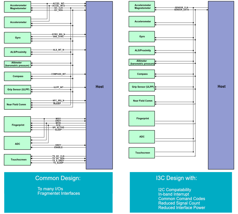
Smartphones and other devices have a rapidly growing number of mechanical, motion, biometric, and environmental sensors that enable a variety of functions and use cases that companies use to differentiate their products. This sensor proliferation creates significant design challenges, especially for software developers. Without a common method of connection, for example, each host controller must have its own system software or its own driver to support this hardware. Each host controller implementation can provide different functions and optimizations.
What is I3C and what advantages does it offer for smartphones?
I3C is a scalable, high-speed utility and control bus interface for connecting peripheral devices to an application processor, optimizing integration, and improving cost efficiency. It offers developers unparalleled opportunities to develop innovative designs for any mobile product - from smartphones to wearables to systems in automobiles.
I3C enables peripheral devices to be connected to an application processor in any mobile device, making it easy to connect and manage multiple sensors in one device. I3C is primarily intended for powerful sensors. In addition, I3C transmits interrupts as a message in the protocol without additional lines. With 10.6 Mbit / s, I3C outperforms I2C by more than three times. The high data rate mode reaches 33 Mbit / s. In some cases, I3C can also replace the more powerful Serial Peripheral Interface (SPI). The advantages of the I3C specification are the lower power consumption, the reduced number of pins and signal paths as well as the high transmission speed with simultaneous downward compatibility with I2C. Device addresses can also be allocated dynamically.
Touch over I3C is a converged interface option for processed and raw touch data. CCI over I3C offers faster, lower latency and more efficient camera control.
I3C signal pins
I3C uses the same two signal pins as I²C, called SCL (serial clock) and SDA (serial data). The main difference is that it works as an I²C open-drain outputs at all times, so its speed is limited by the resulting slow signal rise time. I3C uses open-drain mode for compatibility, but switches to push-pull outputs whenever possible and includes protocol changes to allow this more frequently than in I²C. SCL is a conventional digital clock signal that is controlled by the current bus power master with a push-pull output during data transmission. (Clock stretching, a rarely used I²C function, is not supported.) In transactions with I²C slave devices, this clock signal generally has a duty cycle of approx. 50%. When communicating with known I3C slaves, however, the bus master can switch to a higher frequency and / or a change in the duty cycle, so that the SCL high period is limited to a maximum of 40 ns. SDA transmits the serial data stream, which can be controlled by either the master or the slave, but at a rate that is determined by the master's SCL signal.
For reasons of compatibility with the I²C protocol, every transaction begins with SDA acting as an open drain output, which limits the transmission speed. For messages addressed to an I3C slave, the SDA driver mode changes to push-pull after the first bits in the transaction, so that the clock rate can be increased further to 12.5 MHz. This medium-speed feature is known as Standard Data Rate (SDR) mode. In general, SDA is changed immediately after the falling edge of SCL and the resulting value is received on the following rising edge. When the master transfers SDA to the slave, this also happens on the falling edge of SCL. However, if the slave returns control of SDA to the master (e.g. after confirming its address prior to a write), it releases SDA on the rising edge of SCL and the master is responsible for changing the received value for keep the duration of SCL high. (Since the master drives SCL, the rising edge is displayed first, so that there is a short period of overlap if both control SDAs. However, since both control the same value, no bus conflict occurs.)
I3C framing?
All communications in I²C and I3C require framing for synchronization. Changes on the SDA line should always occur within a frame while SCL is in the low state, so that SDA can be considered stable by SCL when it goes from low to high. Violations of this general rule are used for framing (at least in legacy and standard data rate mode). The bus master holds the SCL high between the data frames, which stops the clock, and the SDA drivers are in a high-resistance state so that a pull-up resistor can raise it to high level. A high-low transition from SDA while SCL is high is referred to as a START symbol and signals the beginning of a new data frame. A low to high transition on SDA while SCL is high is the STOP symbol that ends a data frame. An unprecedented STOP, referred to as a "repeated START", can be used to end one message and begin another within a single bus transaction. In I²C the START symbol is normally generated by a bus master. However, in I3C, even slave devices can pull down the SDA value to indicate that they want to start a frame. This is used to implement some advanced I3C features like in-band interrupts, multi-master support, and hot joins. After the start, the bus master restarts the clock by activating the SCL and begins the bus arbitration process.
Ninth bit I3C
Like I²C, I3C uses 9 clock cycles to send each 8-bit byte. However, the 9th cycle is used differently. I²C uses the last cycle for an acknowledgment, which is sent in the opposite direction to the first 8 bits. I3C works in the same way for the first (address) byte of every message and for I²C-compatible messages. When communicating with I3C slaves, message bytes after the first use are the 9th bit an odd parity bit when writing and an end-of-data flag when reading. Write processes may only be terminated by the master. Either the master or the slave can end a read. The slave sets SDA low to indicate that no more data is available. The master then takes over SDA and generates a STOP or a repeated START. In order for a read to continue, the slave drives SDA high while SCL is low before the 9th bit, but allows SDA to float (open drain) while SCL is high. At this point in time, the master can drive SDA low (a repeated START condition) in order to abort the read process.
I3C bus arbitration
At the beginning of a frame, multiple devices can compete for use of the bus, and the bus arbitration process is used to select which device receives control of the SDA line. In both I²C and I3C, bus arbitration is carried out with the SDA line in open drain mode, which means that devices that transmit a binary 0 (low) can overwrite devices that transmit a binary 1. Competing devices monitor the SDA line while operating in open mode. Drain mode. Whenever a device detects a low state (0 bit) on the SDA while sending a high state (1 bit), it has lost the arbitration and must stop competing until the next transaction begins.
Every transaction starts with the destination address, and the implementation gives lower number destination addresses priority. The difference is that I²C has no limit on the duration of the arbitration (in the rare but legal situation of several devices trying to send a message to the same device, the conflict is only recognized after the address byte). However, I3C guarantees that the arbitration will be completed by the end of the first byte at the latest. This allows push-pull drivers and faster clock speeds to be used most of the time. This is done in different ways: I3C supports multiple masters, but these are not symmetrical. One is the current master and is responsible for generating the clock.
Other devices sending a message on the bus (in-band interrupts or secondary masters wishing to use the bus) must decide using their own address before sending other data. Thus, no two legal bus messages share the same first byte unless the master and another device are communicating with each other at the same time. Like I²C, I3C enables multiple messages per transaction, separated by "repeated START" symbols. Arbitration is per transaction so these subsequent messages are never subject to arbitration. Most I3C master transactions start with the reserved address 0x7E (1111110 2).
Since this has a lower priority than any I3C device, the master knows after successful arbitration that no other device is fighting for the bus. If I3C devices are assigned low addresses as a special case (I3C supports dynamic address assignment controlled by the master), 0x7E the master knows this arbitration as soon as the address has won an arbitration for enough leading bits to distinguish it from an assigned address and it can be switched to push-pull operation on SDA. If all assigned addresses are less than 0x40, this is done after the first bit. If all addresses are less than 0x60, this is done after the second bit and so on.
In the case described above, in which the current master begins a transaction with the address of a device that is itself fighting to use the bus, both of them transmit their address bytes successfully. However, each expects the other to acknowledge the address (by pulling SDA low) for the following acknowledge bit. As a result, neither or both will notice the lack of appreciation. In this case, the message will not be sent, but the master wins the arbitration: a retry start may be sent, followed by a retry that will be successful.
I3C General command codes
A 0x7E write addressed to the reserved address is used to perform a number of special operations in I3C. All I3C devices must receive and interpret write operations to this address in addition to their individual addresses. Firstly, a write process that consists only of the address byte and no data bytes has no effect on I3C slaves, but can be used to simplify I3C arbitration. As described above, this prefix can speed up the arbitration (if the master supports optimizing the switch to push-pull midbyte), and it simplifies the master by avoiding a somewhat tricky arbitration case. If the write is followed by a data byte, the byte encodes a "general command code", a standardized I3C operation. Command codes 0–0x7F are broadcast commands that are addressed to all I3C slaves.
They can be followed by additional command-specific parameters. Command codes 0x80-0xFE are direct commands that are addressed to individual slaves. This is followed by a series of repeated STARTs and writing or reading in certain slaves. While a direct command is being executed, write or read processes transmit command-specific parameters per slave. This operation replaces the slave's normal response to an I3C message. A direct command can be followed by several messages per slave, each of which is preceded by a repeated START. This special mode ends at the end of the transaction (STOP symbol) or the next addressed message 0x7E. Some command codes exist in both broadcast and direct form. For example, the commands for activating or deactivating in-band interrupts can be sent to individual slaves or sent to all. Commands to get parameters from a slave (e.g. the GETHDRCAP command to ask a device which high data rate modes are supported) are only available in direct form.
I3C HDR-Optionen (High Data Rate)
Every I3C bus transaction starts in SDR mode, but the I3C master can issue a CCC broadcast command "Enter HDR" which tells all I3C slaves that the transaction will continue in a specific HDR mode. I3C slaves that do not support HDR can then ignore the bus traffic until they see a certain "HDR exit" sequence informing them that it is time to hear the bus again. (The master knows which slaves support HDR and will therefore never attempt to use HDR to communicate with a slave who does not support it.) Some HDR modes are also compatible with I²C devices if the I²C devices have have a 50 ns spike filter in the SCL line. That is, they ignore a high level on the SCL line that lasts less than 50 ns. This is required in the I²C specification, but is not implemented universally, and not all implementations ignore frequent repetitive peaks.
Therefore I3C-HDR compatibility needs to be checked. The compatible HDR modes use SCL pulses of 45 ns or less, so I²C devices ignore them. HDR DDR mode uses double data rate signaling with a 12.5 MHz clock to achieve a raw data rate of 25 Mbit / s (effectively 20 Mbit / s). This requires changing the SDA line while SCK is high, a violation of the I²C protocol, but I²C devices do not see the short high pulse on SCL and therefore do not notice the violation. The HDR-TSP and HDR-TSL modes use one of three symbols as ternary digits (trits):
A transition from SDA and SCL (received within 12.8 ns of each other), Only one transition from SCL, or Only one transition from SDA. Two bytes plus two parity bits (18 bits total) are divided into six 3-bit triplets, and each triplet is encoded as two trits. At a speed of 25 Mbit / s, an effective data rate of 33.3 Mbit / s is achieved. The trit pair, which consists of just two transitions of SDA, is not used to encode data but is used for framing to mark the end of an HDR sequence. Although this limits the maximum time between SCL transitions to three trit times, it exceeds the 50 ns limit for older I²C devices. Therefore the HDR-TSP mode (ternary symbol, pure) can only be used on a bus without older I²C devices. To allow buses with I²C devices (with a peak filter) the HDR TSL mode (ternary symbol, legacy) must be used. This means that I²C compatibility is retained through trit stuffing: If the following trit is not 0 after a rising edge at SCL, a 1 trit (only transition for SCL) is inserted by the transmitter and ignored by the receiver. This ensures that the SCL is never high for more than a trit time.
Device classes
Four different device classes can be supported on an I3C bus in standard mode (SDR):
- I3C main master
- I3C Secondary Master
- I3C slave
- I²C slave (older devices).
The following I²C functions are not supported in I3C
Pull-up resistors are provided by the I3C master. External pull-up resistors are no longer required. Clock Stretching - Devices are expected to be fast enough to operate at bus speed. The I3C master is the only clock source. Extended I²C addresses (10 bit). All devices on an I3C bus are addressed with a 7-bit address. Native I3C devices have a unique 48-bit address that is only used for dynamic address assignments.
I3C Host Controller Interface
I3C HCI defines a common set of functions for the host controller and software interface that can be used to create class definitions based on a common set of functions. The definition enables manufacturer-specific expansions and optimizations in order to more easily integrate added value functions for smartphones, wearables, Internet of Things (IoT) and automobiles and more. The specification provides the platform software with an efficient means of communicating with the functions of the master device on the I3C bus and ensures low-power operation of the host controller. The bottom line: Developers have time to focus on integrating the camera, touch, and other components and functions to differentiate their products. "
I3C Touch and Camera
I3C contains numerous specifications specially designed for the mobile industry. These specification extensions for special applications extend, for example, from touch to camera connections and enable developers to implement it more easily and to save costs during development.
I3C HCI, is also part of the I3C Touch family of specifications so that touch commands and multiple data streams can be used to add differentiating touch functionality to a design. Application processor companies can use the specification to standardize the HCI methodology used in their devices. The specification defines several optimizations based on typical usage. For example, the combination command function enables the efficient one-time transfer of write and then read transfers on the bus. Another example is the automatic instruction that can efficiently read a large data buffer in connection with in-band interrupts.
I3C Protocol Analyzer and Host Adapter
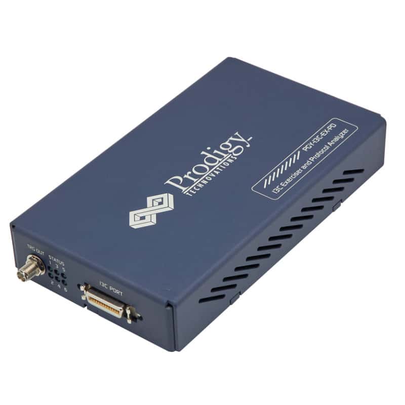
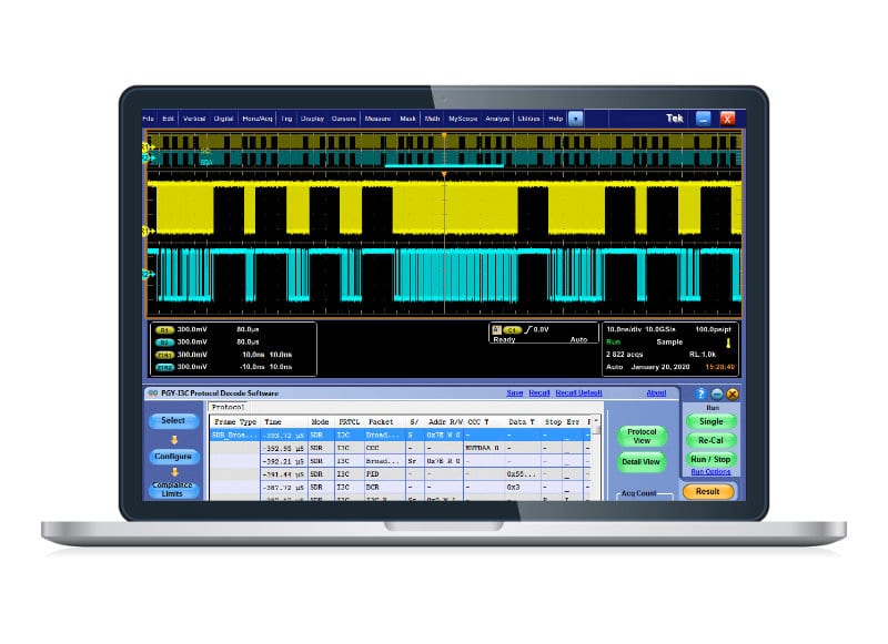
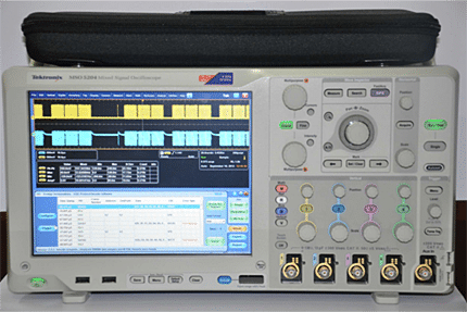
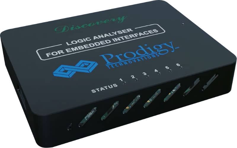
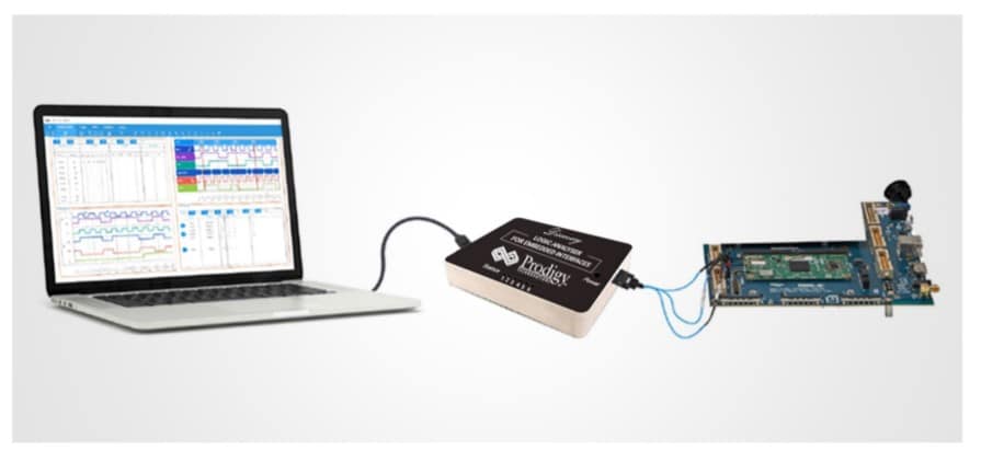
PGY-I3C-EX-PD is the premier tool that allows designers and test engineers to test the I3C designs for their specifications by configuring PGY-I3C-EX-ED as master / slave, generating I3C traffic with fault injection function, and I3C decode protocol decoding packets.
Price on request
Price on request
