What is a Logic Analyzer?
A logic analyzer is an electronic measuring device that can mark and display digital signals over time. A logic analyzer is often used for testing or troubleshooting in digital electronic circuits.
Before we move on to the basics of how a logic analyzer works, the basic structure of a logic analyzer must be clarified.
A logic analyzer usually consists of two main units, i.e. two analyzers. One part is a timing analyzer, while the second is a condition analyzer.
The timing analyzer
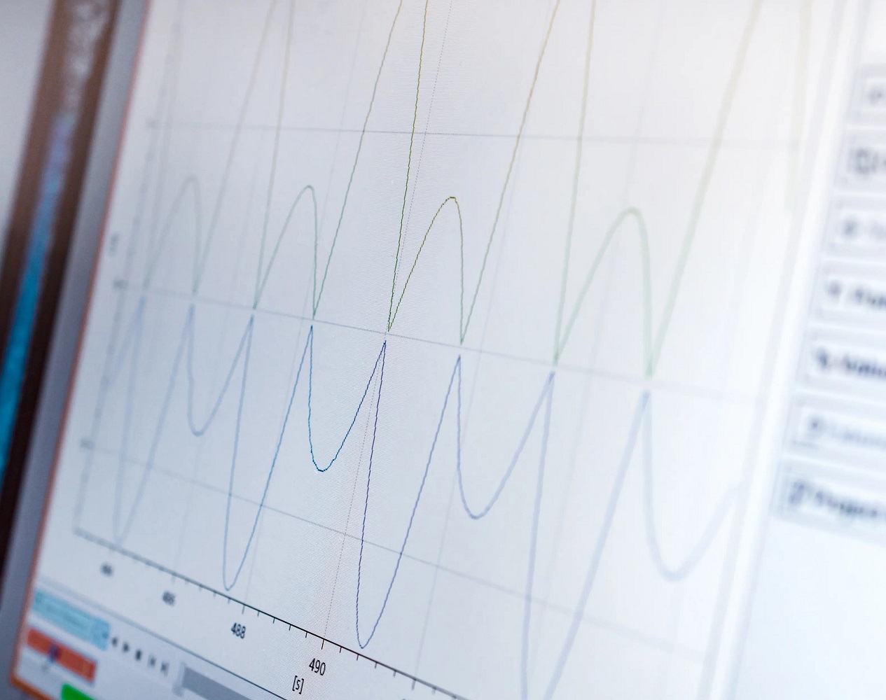
In general, a timing analyzer displays information in the same way and shape as an oscilloscope. In this general form, the horizontal axis represents time and the vertical axis represents voltage amplitude. The respective display is in the time domain, since the waveforms of both instruments are time-dependent.
The digitization range of a timing analyzer is similar to that with 1 bit vertical resolution. Since only a single bit is available for vertical resolution, two different states can be displayed. High or low (0 or 1). The defined threshold values (voltage) are individual user-defined values. The incoming signals are classified according to whether they are above the threshold (1) or below the threshold (0).
From these sampled points, the timing analyzer creates a list of ones and zeros, which is a one-bit image of the input signal function. This generated list is stored in the internal memory of the device and used to reconstruct a one-bit image of the input.
The state analyzer
A "state" for a logic circuit is a sample of a bus or line if its data is valid. Consider a simple "D" flip flop. Data at input "D" are only valid when a positive clock edge occurs. A state for the flip-flop is therefore when the positive clock edge occurs.
Imagine there are eight of these flip-flops in parallel and they are all connected to the same clock signal. When a positive transition occurs on the clock line, collect all eight data at their "D" inputs. Again, a condition occurs every time there is a positive transition on the clock line. These eight lines are analogous to a microprocessor bus. If a state analyzer is connected to these eight lines and instructed to collect data when there is a positive transition on the clock line, the analyzer would do just that. Activities at the inputs are only recorded by the condition analyzer when the clock starts up.
The timing analyzer has an internal clock to control the sampling so that the system under test is sampled asynchronously. A state analyzer samples the system synchronously because it receives its sampling clock from the system.
A state analyzer generally displays data in a list format and a time analyzer displays data as a waveform diagram.
Understanding clocks: In the timing analyzer, sampling is done under the guidance of a single internal clock. That makes things very easy. In the world of microprocessors, however, a system can have multiple "clocks".
Suppose a technician wants to trigger a specific address in RAM for a moment and see what data is stored there. Let's say the system uses a Zilog Z80. To capture addresses from the Z80 with a condition analyzer, it must be captured when the MREQ line goes low. However, to collect data, the analyzer should sample when the write cycle line (WR) goes low or when the read cycle (RD) goes low. Some microprocessors multiplex data and addresses on the same lines. The analyzer must be able to enter information from the same lines but from different clocks.
What types of logic analyzers are there?
Since a logic analyzer is one of the most popular measuring devices in electronics today, there are a variety of versions. In the upper price segment you will find devices that can work independently without a PC and often have more than 34 logical channels. For simple applications, one device that is connected to the PC via the USB bus is usually sufficient. A particularly experienced manufacturer of logic analyzers is the company Prodigy, which provides all customers with free analyzer software that comes up with a huge library of additional protocols that can be analyzed. Prodigy offers the PGY-LA-EMBD Logic Analyzer, the industry's first in its category logic analyzer, allowing engineers to troubleshoot timing issues and perform simultaneous protocol analysis of I2C, SPI, UART, I3C, RFFE & SPMI interfaces in embedded designs can. This allows designers to quickly troubleshoot circuit and system level problems.


