Enhanced Serial Peripheral Interface (eSPI)
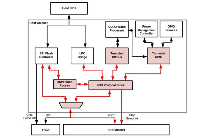
Industry leader Intel defines the new eSPI standard as an improvement in data transactions with lower power consumption and lower costs. Manufacturers can easily integrate this - at the chip, board and system level - into their products.
SPI Definition
SPI devices communicate in full-duplex mode using a master-slave architecture (alternate terminology as the main and secondary languages) with a single master. The master device creates the frame for reading and writing. Multiple slave devices are supported by selecting individual slave select lines (SS), sometimes called chip select lines (CS).

Features
The functions include a four-wire interface (receive, transmit, clock and slave selections) and three configurations:
Single I / O (or standard I / O): clock, chip select, unidirectional data signal (MOSI), unidirectional data signal (MISO)
DUAL IO: clock, chip selection, bidirectional data signal (IO0), bidirectional data signal (IO1)
QUAD IO: clock, chip selection, bidirectional data signal (IO0), bidirectional data signal (IO1), bidirectional data signal (IO0 = 2), bidirectional data signal (IO3)
eSPI: Where are the advantages?
With its significantly lower voltage level of 1.8V to 3.3V, its low pin count and twice the operating frequency of 66MHz versus 33MHz, the technological advances of the new eSPI standard are enormous. Due to these technical advantages, eSPI is intended to replace the Lower Pin Count (LPC) interface, which has been used in the computer market for more than 15 years and is considered the standard.
The lower signal level reduces the required power. Also, the signal noise that often occurs at higher clock rates is suppressed. The reduced pin count of the tracks needed on the PCB. eSPI requires a maximum of 8 pins for one slave: chip select, clock, 4 data lines, alarm (optional) and reset.
The accelerated clock rate allows more bandwidth for data transfer and faster operations: 4x 66 MHz.
To meet product requirements, system designers can choose the maximum supportive clock rate: 20, 25, 33, 50 or 66 MHz.
With the stability of a particular industry-wide standard, the eSPI can support the future development of client and server platforms, including peripherals and storage, over many years.
