Guide to High Resistance & Microcurrent Testing
Introduction
Careful reading of the instructions and this guide will help you to perform correct and reliable high resistance and micro current tests.
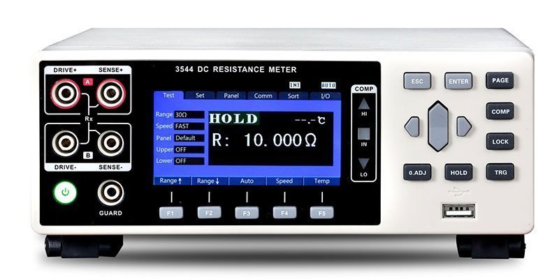
Note: Hopetech's HT3544 high precision resistance tester was used for the measurements.
In the voltage addition method for current measurement, the voltage output is 1mV ~ 1000V DC and the internal resistance of the source is 100kΩ.
The resistance measurement range up to 10Ω ~ 1015Ω and the current measurement range 2mA ~ 1pA, can effectively have small resolution up to 10fA.
Measurement functions also include a range of surface insulation resistance tests, surface resistance measurements of insulating materials and semiconductors, and volume resistance measurements as well as volume resistance measurements.
| Measuring range | Resolution | Accuracy ±(%+ resolution) | Temperature coefficient(ppm/℃) |
|---|---|---|---|
| 2 mA | 0,1 µA | 0,1+5 | 25 |
| 200 µA | 10 nA | 0,1+5 | 25 |
| 20 µA | 1 nA | 0,1+5 | 25 |
| 2 µA | 0,1 nA | 0,1+10 | 50 |
| 200 nA | 10 pA | 0,1+10 | 50 |
| 20 nA | 1 pA | 0,3+20 | 200 |
| 1 nA | 0,01 pA | 5+20 | 200 |
| Measuring range | Resolution | Accuracy ±(%+ resolution) | Temperature coefficient(ppm/℃) | Test voltage |
|---|---|---|---|---|
| 10 kΩ | 1 Ω | 0,1+5 | 25 | 50 V |
| 100 kΩ | 10 Ω | 0,1+5 | 25 | 50 V |
| 1 MΩ | 100 Ω | 0,1+5 | 25 | 50 V |
| 10 MΩ | 1 kΩ | 0,1+5 | 50 | 50 V |
| 0,1 GΩ | 10 kΩ | 0,1+5 | 50 | 50 V |
| 1 GΩ | 100 kΩ | 0,1+10 | 50 | 500 V |
| 10 GΩ | 1 MΩ | 0,35+20 | 50 | 500 V |
| 100 GΩ | 10 MΩ | 0,35+20 | 200 | 500 V |
| 1 TΩ | 10 GΩ | 2+100 | 200 | 1000 V |
| 10 TΩ | 100 GΩ | 5+1000 | 200 | 1000 V |
| 100 TΩ | 1 TΩ | 10+1000 | 500 | 1000 V |
| 1000 TΩ | 10 TΩ | 20+1000 | 500 | 1000 V |
If accurate and reliable test results are to be achieved, not only the high accuracy of the test device itself and advanced test principles are important, but also the right test methods and a suitable test environment. The essence of high resistance testing is to test micro currents that are very sensitive to environmental, dielectric and material factors.
1.) The preparation for high-impedance measurements
Before carrying out high resistance measurements, the following should be noted.
a.) Selection of the environment
When performing high resistance tests, it is recommended that the user perform the test in dry air to obtain an accurate measurement of the resistance of the item under test. Although the front-end amplifier of the CHT3530 is housed in a waterproof metal enclosure, moist air can contaminate the test probe and the test object and affect the accuracy of the test.
The test environment must avoid mechanical vibration, which can cause friction between the inner core of the test lead and the frequency shield, resulting in static friction interference.
b.) Preparation of the fixtures
Before testing, please prepare the test fixture. If you need to test high resistance, please prepare the electrostatic box. Contaminated fixtures may cause a drop in insulation resistance due to electrochemical effects, resulting in test errors or failure. It is recommended to clean contaminated fixtures with a small amount of a volatile organic solvent (e.g. methanol).
c.) Electrostatic shielding
Electrostatic coupling and interference can occur when a charged object is near the input of the circuit under test. At low impedance, the effect of interference is insignificant because the charge dissipates quickly. However, with high-impedance materials, the charge cannot be dissipated quickly, which can lead to unstable measurement results. Since erroneous readings can be caused by electrostatic DC or AC fields, electrostatic shielding helps to minimise the effects of such fields. If available, we recommend that the user perform the test in an electrostatic chamber. If this is not possible, it is recommended to place a metal plate under the object to be tested and connect this to the frequency shielding, which also provides good protection against static electricity.
d.) Connect the mains cable and the test lead correctly
Make sure that the mains cable of the unit has a good earth connection. Poor earthing of the unit and strong common mode interference will affect the accuracy and stability of the test. After switching on, the voltage output is switched off. For your safety, do not open the charging button until the test leads are connected.
Connect the correct number of test leads according to the instructions. If you are using an electrostatic box, please connect the wiring correctly to the electrostatic box.
2.) Test steps
a.) Switching on and warming up
In order to achieve the rated accuracy and stability of the device, the device must be warmed up for 15 minutes before starting the measurement. rmt.
b.) System zero calibration
If the front-end amplifier is not corrected for "zeroing", the resulting bias will overwhelm the input signal and generates an error due to the presence of detuned voltage and current. Distortion is usually expressed as a function of time or temperature. The zero offset over a given time and temperature range should be within the specified limits. Distortions caused by temperature jumps can exceed the specified specification before reaching stability. A typical room temperature change rate (1°C/15 minutes) does not normally lead to such overshoots. A system zero is usually only required when the device is first powered up or after a prolonged period of testing due to a large environmental change.
Execution: Enter the system calibration icon without entering the password to access the menu; and hold the test lead in a good open circuit for 5 seconds (5 seconds is the setup time described in the following section), press OK to perform the system zero and wait until the zero adjustment has reached 100% before you enter the menu. leave.
c.) Delete the background current (panel reset)
Background current is the drift of the base due to changes in bias current caused by factors such as changes in leakage from protective devices, test leads, etc., or changes in test environment or changes in electric field caused during the exam. The input bias current is superimposed on the current under test, so the meter measures the sum of the two currents: IM = IS + IOFFSET.
some of the factors. When removing background current, try to keep all live objects (including people) and conductors away from the sensitive areas of the test circuit and avoid movement and vibration near the test area.
if the gauge end is open and has a large base, you must zero it. This can be done by pressing the "Delete" button on the test screen. Do not touch or shake the test leads when performing a clear, but hold the test leads well open. It is a good idea to leave the test leads hanging until the setup time has elapsed and the plate count is stable. Note: There is a difference between system zeroing and panel zeroing.
d.) System Zeroing
System zeroing is achieved by adjusting the internal bias of the device, which improves the linearity of the device and reduces misalignment will. Zeroing the display is a simple subtraction operation to subtract the base of the display. Connecting the EUT The EUT is placed in an electrostatically shielded environment (to avoid interference from static fields), and the EUT and the shield are placed in a highly isolated condition that prevents the measured current from flowing is bridged.
Try to avoid excessive twisting of the sample line, as the cover line creates a piezoelectric effect when twisted and static friction when slowly stretched, which can lead to test errors or erratic readings.
Voltage output
On the measurement screen, press the "Voltage setting" button and input the test voltage you want. Make sure the test terminal is open, and press the "charge/discharge" button to output the voltage, which is then output from the high voltage output.
e.) Test start
It is normal for the test to take some time to stabilize. This time is related to the resistance and stray capacitance of the test object and the material properties of the test object and is usually referred to as build-up time b
3.) The setup time
The circuit set-up time is particularly important when measuring high resistance. The build-up time of the measurement is influenced by the parallel capacitance
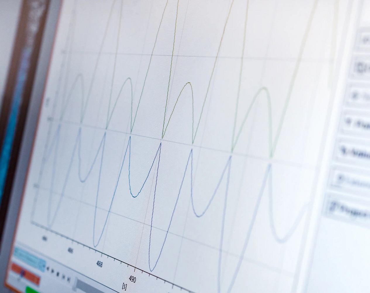
which is generated by the connection cable, the test device and the device under test. The parallel capacitance (C) must be charged to the test voltage by the test current (I). The time required to charge the capacitor is determined by the RC time constant (doubling time constant) and gives the well-known exponential curve. This requires a waiting time of 4 to 5 times the time constant before an accurate reading is obtained. When measuring very high resistance values, the setup time can be several minutes, depending on the value of the shunt capacitance in the test system. if e.g. For example, if C is 10pF, the time constant for measuring a resistance of 1T? 10 seconds. Therefore, a build-up time of 50 seconds is required to stabilize the reading to 1% of full scale. In order to minimize the setup time when measuring high-impedance resistances, the connection cables are kept as short as possible so that the parallel capacitance in the system is actually as small as possible. In addition, setup time can be significantly reduced through the use of protection techniques. Finally, resistance measurements are generally faster with the voltage and current measurement methods due to the reduced setup time.
Note: In order to get more accurate and stable measurements, it is recommended to set the device test speed to "slow", the average number of tests to "20", and when testing new products wait for a start-up time of about 30-50 seconds before looking at the measurement data.
4.) Test the connection
The cable between the input end of the instrument and the device under test must also be shielded. The capacitive coupling between the electrostatic noise source and the signal conductor or cable can be greatly reduced by enclosing the signal conductor in a metal shield that is connected to the ground end. With this shield, the noise currents generated by the electrostatic voltage source and the coupling capacitors flow through the shield to ground and no longer through the signal line.
In general, adhering to the following guidelines can minimize the current generated by electrostatic coupling:
In general, the following guidelines can be followed to minimize the currents generated by electrostatic coupling.
* Keep all live objects (including people) and conductors away from the sensitive areas of the test circuit.
* Avoid movement and vibration near the test area.
* If the measured current is less than 1nA, shield the device under test by surrounding it with a metal cap and connecting this cap to the common end of the test circuit. If an insulated electrode test box is available, the part to be tested can be placed in the electrode box for testing.
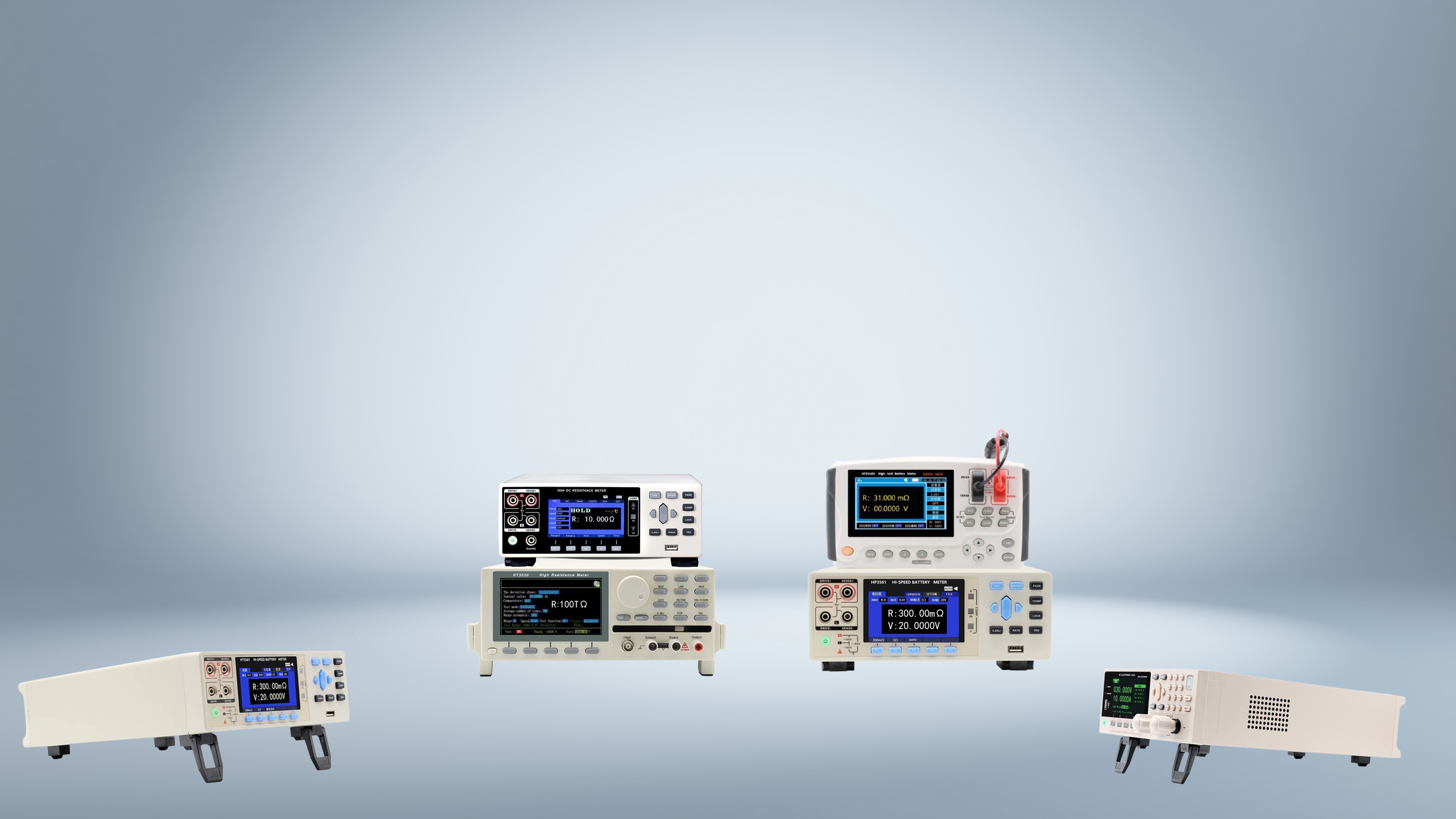
Resistance tester series HT3544
The HT3544 Precision DC Resistance Tester is one of the most accurate DC Resistance Testers in the industry. The HT3544 DC Resistance Tester has a 3.5 inch display and has a measuring range of 3mΩ. to 3 MΩ. Due to the minimum resolution of 0.1 µΩ and a measurement accuracy of 0.02%, the resistance tester is well suited for inspection of converter motors and other applications that require high-resolution resistance measurement. Equipped with RS232/RS485/LAN interfaces and EXT I/O port, the devices of the HT3544 resistance tester series are suitable for performing automatic tests in test or production lines.

